
A concrete garage floor can remain painfully cold long after the surrounding air begins to warm.
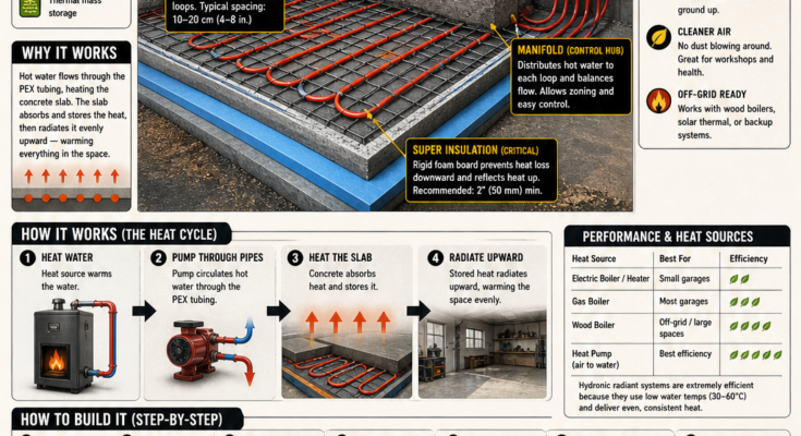
Hydronic radiant-floor heating addresses that problem by circulating heated fluid through tubing embedded in or attached beneath the floor. Instead of blowing hot air from a ceiling-mounted heater, the system warms the concrete slab. The slab then releases heat gradually into the garage.
The basic principle is:
Heat source + circulation pump + PEX tubing + insulated slab = steady radiant warmth
A properly designed system can provide:
- Warm, comfortable floors
- Quiet operation
- Fewer noticeable hot and cold spots
- Reduced air movement
- Useful thermal storage in the concrete
- Compatibility with several heat sources
- Independent temperature zones
- Lower operating temperatures than many conventional hydronic emitters
However, installing tubing in concrete is not a casual weekend experiment.
Once the concrete is poured, correcting a bad tube layout, damaged loop, inadequate insulation, or missing control becomes difficult and expensive. The tubing plan, heating load, water temperature, pump size, manifold, insulation, controls, and heat source should therefore be designed as one complete system.
What Is Hydronic Radiant-Floor Heating?
A hydronic radiant floor uses heated water—or an approved water-and-antifreeze mixture—to transport energy beneath the floor.
The system normally includes:
- A boiler, hydronic heat pump, or another approved heat source
- A circulation pump
- Supply and return piping
- One or more continuous PEX loops
- A distribution manifold
- Air-removal equipment
- An expansion tank
- Pressure-relief and safety controls
- A thermostat or slab sensor
- Insulation beneath and around the slab
Warm fluid leaves the heat source, travels through the supply manifold, circulates through the floor loops, and returns at a lower temperature. The heat source then reheats the fluid and repeats the cycle.
Radiant floors warm the floor surface and surrounding objects while also heating the room air. ASHRAE defines a radiant heating system as one that transfers heat primarily through infrared radiation. ASHRAE terminology
Why Radiant Heat Works Well in a Garage
Garages and workshops often have conditions that make conventional heating difficult:
- Tall ceilings
- Large overhead doors
- Frequent air leakage
- Cold concrete floors
- Vehicles introducing snow and moisture
- Workers spending long periods close to the floor
- Intermittent use
- Dust created by sanding, cutting, or vehicle work
A forced-air heater warms the air first. When the overhead door opens, much of that warm air can escape quickly.
A heated slab also loses energy when the door opens, but the concrete retains some stored heat. After the door closes, the warm thermal mass can help the garage recover.
Additional advantages include:
Quiet operation
The floor itself has no fan. Pumps and boilers may still make some sound, but a properly designed system is usually quieter than a large unit heater.
Less air movement
Radiant heat does not depend on a powerful blower to distribute heat. That can reduce the movement of workshop dust, although it does not replace ventilation or dust collection.
Even floor-level comfort
Heat is delivered across a broad surface rather than from one hot appliance mounted on a wall or ceiling.
Lower water temperatures
Radiant slabs can often operate with lower-temperature water than traditional baseboard radiators. The actual temperature must be calculated for the building and floor assembly.
Multiple heat-source options
Depending on local availability and system design, the floor may be supplied by:
- A condensing boiler
- An electric boiler
- An air-to-water heat pump
- A ground-source heat pump
- A properly designed biomass or wood-boiler system
- Solar thermal equipment combined with reliable backup heat
A wood boiler is not automatically “off-grid.” Most hydronic systems still require electricity for pumps, controls, valves, and safety equipment unless a qualified designer provides approved backup power or a specialized system.
The Concrete Slab as a Thermal Battery
Concrete has considerable thermal mass. Once heated, it stores energy and releases it gradually.
This can produce steady temperatures, but it also creates an important limitation:
A thick heated slab responds slowly.
Turning up the thermostat may not make the garage warm immediately. Depending on the slab, insulation, tubing depth, outdoor conditions, and heating capacity, noticeable changes may take hours.
Likewise, the slab may continue releasing heat after the thermostat stops calling for warmth. Poor control design can therefore cause overheating.
ASHRAE notes that radiant floors can smooth temperature changes, but inadequate floor design or controls can also contribute to overheating and higher energy use. ASHRAE radiant-floor research summary
Radiant slabs work best when operated steadily rather than repeatedly switched between very cold and very hot settings.
Start With a Heating-Load Calculation
Do not size the system from the garage’s square footage alone.
Two garages of identical size can have dramatically different heating requirements because of differences in:
- Climate
- Design outdoor temperature
- Ceiling height
- Wall and ceiling insulation
- Slab-edge insulation
- Window area
- Overhead-door construction
- Air leakage
- Door-opening frequency
- Desired indoor temperature
- Exposure to wind
- Attached versus detached construction
A room-by-room or zone-specific heating-load calculation estimates how many British thermal units per hour the garage loses during design conditions.
That calculation helps determine:
- Required floor output
- Tube spacing
- Supply-water temperature
- Number and length of loops
- Flow rate
- Pump head
- Boiler or heat-pump capacity
- Whether the floor alone can heat the space
A garage with poor insulation and frequently opened doors may lose heat faster than a comfortable floor can safely deliver it. In that case, the building may need:
- Better insulation and air sealing
- A higher-performance overhead door
- A separate recovery heater
- A lower indoor temperature target
- A combination of radiant and supplemental heat
Do not force the slab to compensate for an inefficient building envelope by simply sending dangerously hot water through it.
Insulation Is Critical
Without appropriate insulation, part of the heat intended for the garage will travel downward into the soil and sideways through the slab edge.
A typical new heated-slab assembly may include:
- Compacted granular base
- Moisture-control layer or vapor retarder
- Code-compliant rigid insulation
- Reinforcement or tubing supports
- PEX heating loops
- Concrete slab
- Finished or sealed surface
The precise order and materials depend on climate, soil, foundation design, local code, and the specifications of the structural and insulation products.
Under-slab insulation
Rigid insulation beneath the slab separates the heated concrete from the ground.
The required R-value should be established by local energy codes and the project designer. The frequently repeated recommendation of “two inches of foam” is not universal. Insulation products have different R-values, compressive strengths, moisture resistance, and allowable uses.
Use insulation rated for:
- Below-grade or under-slab installation
- Expected vehicle and slab loads
- Long-term moisture exposure
- Local soil conditions
- The specified concrete assembly
Slab-edge insulation
The slab perimeter can be a major path for heat loss because the concrete edge is closer to cold exterior air.
Continuous edge insulation should be detailed carefully, while also considering:
- Termite-inspection requirements
- Fire protection
- Exterior finish
- Moisture drainage
- Door thresholds
- Vehicle loads
- Local building codes
A U.S. Department of Energy Building America case study used continuous R-10 insulation below a radiant slab and R-7 insulation at its edge, illustrating the importance of controlling both downward and perimeter losses. Those values are an example, not a universal specification. DOE Building America case study
Choose the Correct Tubing
PEX is commonly used because it is flexible, corrosion-resistant, and available in long coils that allow each floor circuit to be installed without concealed joints.
For a closed-loop heating system, use tubing approved for hydronic heating. Oxygen-barrier PEX is commonly specified when the system contains ferrous components such as cast-iron pumps or steel boilers.
The oxygen barrier helps limit oxygen entering through the tube wall and contributing to corrosion.
Common tubing sizes
Many garage slabs use 1/2-inch PEX, but larger or smaller tubing may be appropriate in some systems.
Tubing size affects:
- Maximum practical loop length
- Flow resistance
- Pump selection
- Bend radius
- Heat delivery
- Manifold connections
Follow the tubing manufacturer’s design and installation documentation.
Avoid fittings beneath the slab
Each circuit should normally be one continuous length from the supply manifold, through the floor, and back to the return manifold.
Do not intentionally bury couplings, elbows, valves, or improvised repairs in concrete unless an approved system and qualified designer specifically permit it.
Protect the tubing
Tubing can be damaged by:
- Sharp reinforcement wire
- Careless fastening
- Vehicle traffic before the pour
- Concrete tools
- Rebar chairs
- Kinked bends
- Welding sparks
- Nails or screws
- Ultraviolet exposure during prolonged outdoor storage
Use bend supports, sleeves, and protective conduit where tubing enters or leaves the slab.
Plan the Tubing Layout
The layout must be completed before installation.
A good plan identifies:
- Manifold location
- Number of circuits
- Length of every loop
- Tube spacing
- Supply and return routes
- Expansion or control joints
- Floor drains
- Vehicle-lift anchors
- Partition walls
- Plumbing penetrations
- Future equipment mounting points
- Areas that should not be heated
Typical spacing
Many residential and light-commercial radiant slabs use tube spacing somewhere around 6 to 12 inches on center. Closer spacing may increase and even out heat delivery, while wider spacing may reduce material but create greater surface-temperature variation.
The infographic’s 4-to-8-inch spacing should not be copied automatically. Four-inch spacing is unusually tight for many garage projects and can increase tubing length and pumping resistance.
Spacing must be based on:
- Calculated heat loss
- Water temperature
- Floor construction
- Tubing depth
- Floor-covering resistance
- Desired surface temperature
- Maximum loop length
Use a counterflow spiral when appropriate
A spiral or “snail” pattern places hotter supply tubing beside cooler return tubing, promoting more even floor temperatures.
A serpentine pattern is easier in some spaces, but it may leave the supply side warmer than the return side. It can be useful when the hottest water is intentionally placed along a cold exterior wall or overhead door.
Keep loops reasonably balanced
Loops connected to the same manifold should have similar pressure-loss characteristics. One very short loop paired with several extremely long loops may be difficult to balance.
Flow meters and balancing valves can help, but good planning begins with sensible loop lengths.
Avoid tight bends
Follow the manufacturer’s minimum bend radius. Never force a kinked tube back into service without following the manufacturer’s approved repair instructions.
Areas Where Tubing Should Usually Be Avoided
Do not place PEX wherever future drilling or anchoring is expected.
Possible exclusion zones include:
- Vehicle-lift posts
- Permanent machine bases
- Floor-mounted cabinets
- Structural columns
- Toilet or sink penetrations
- Floor drains
- Expansion joints
- Control joints
- Saw-cut locations
- Future partition walls
- Anchored stairs or railings
- Garage-door tracks and posts
Mark these areas on the plan before installing the tubing.
After installation, photograph the entire layout from several angles and record measurements from fixed walls. Store the plan permanently.
A thermal camera or tube-locating equipment can help later, but accurate construction records are more dependable than memory.
Locate the Manifold Carefully
The manifold is the control and distribution hub for the floor.
It divides heated water among the loops and may include:
- Supply and return headers
- Isolation valves
- Flow meters
- Balancing valves
- Actuators
- Temperature gauges
- Air vents
- Drain and purge valves
- Pressure gauges
Choose a location that is:
- Accessible after construction
- Protected from freezing
- Protected from vehicle impact
- Close enough to keep loop lengths manageable
- Above expected flood or wash-down exposure
- Large enough for valves and service work
- Away from electrical hazards
Do not bury the manifold behind a finished wall without an accessible service panel.
Select the Heat Source
The heat source must match both the heating load and the low-temperature requirements of the floor.
Condensing boiler
A correctly designed radiant system can work well with a condensing boiler because low return-water temperatures may improve condensing performance.
The boiler still requires proper:
- Venting
- Combustion air
- Gas or fuel supply
- Condensate disposal
- Pumping
- Controls
- Annual maintenance
Fuel-burning equipment should be selected and installed by qualified professionals.
Electric boiler
An electric boiler is relatively simple and avoids on-site combustion, but operating cost depends heavily on local electricity prices.
The building’s electrical service must be able to support the added load.
Air-to-water heat pump
A hydronic heat pump can be efficient when paired with low water temperatures, but its output and efficiency may decrease in extremely cold conditions.
The designer should confirm:
- Cold-weather capacity
- Required backup heat
- Water-temperature limits
- Buffer-tank needs
- Defrost behavior
- Electrical demand
Ground-source heat pump
Ground-source equipment can supply low-temperature radiant floors efficiently, but installation cost and site requirements are substantial.
Wood or biomass boiler
A wood boiler can be useful where fuel is available, but safe integration may require:
- Thermal storage
- Overheat protection
- Return-temperature protection
- Approved venting and chimney
- Mixing controls
- Freeze protection
- Backup power
- Separation from occupied garages
- Compliance with emissions and insurance requirements
Do not connect homemade pressurized vessels or improvised wood heaters to an occupied building.
Solar thermal
Solar thermal energy can preheat water or contribute to a heating system, but winter solar availability rarely matches heating demand perfectly. A properly controlled backup source is normally required.
Do Not Use a Household Water Heater Automatically
Some water heaters are approved for certain combined or space-heating applications, but many are not.
Before using one, confirm:
- The appliance is listed for the intended purpose.
- The manufacturer permits space heating.
- Local plumbing and mechanical codes allow it.
- The system prevents contamination.
- Required controls and separation are provided.
- Capacity matches the heating load.
- Warranty conditions are satisfied.
Do not circulate domestic drinking water through a stagnant garage-floor loop unless the entire system has been specifically designed and approved for that arrangement.
A dedicated closed hydronic loop is generally easier to protect, treat, and control safely.
Essential Mechanical Components
A radiant floor requires more than a heater, pump, and tubing.
Depending on the design, the mechanical system may need:
- Expansion tank
- Pressure-relief valve
- Air separator
- Automatic or manual air vents
- Fill valve
- Backflow preventer
- Pressure gauge
- Temperature gauges
- Isolation valves
- Purge valves
- Check valves
- Mixing valve
- Hydraulic separator or closely spaced tees
- Zone valves or circulators
- Outdoor-reset control
- Slab-temperature sensor
- High-temperature limit
- Low-water cutoff
- Freeze-protection controls
The exact arrangement depends on the heat source and local code.
A pressure-relief valve must never be capped, isolated, undersized, or routed to an unsafe location.
Step-by-Step Installation Overview
This overview is intended to help property owners understand and supervise a project. It does not replace an engineered plan, appliance instructions, local permits, or qualified plumbing, electrical, concrete, and HVAC work.
Step 1: Complete the design
Before excavation, establish:
- Design heat loss
- Insulation values
- Slab thickness and reinforcement
- Required floor output
- Supply and return temperatures
- Tube spacing
- Number of loops
- Loop lengths
- Flow rate
- Pump selection
- Manifold location
- Control strategy
- Heat-source capacity
- Freeze-protection plan
Obtain required building, mechanical, electrical, plumbing, or energy permits.
Step 2: Prepare the base
Excavate and compact the base according to the structural plan.
Poor compaction can contribute to:
- Slab settlement
- Cracking
- Broken drains
- Damaged insulation
- Stress on tubing penetrations
Install drainage and moisture-control components as specified.
Step 3: Install the vapor retarder
The vapor retarder helps control ground moisture moving into the slab.
Use the product and thickness required by the slab design and code. Seal or detail seams and penetrations according to the manufacturer’s instructions.
Do not assume the insulation itself replaces the required vapor-control layer.
Step 4: Install under-slab and perimeter insulation
Lay the approved rigid insulation over a stable, level surface.
Keep joints tight and stagger layers when specified. Avoid broken corners, rocking boards, and large gaps.
Complete the slab-edge detail before tubing installation.
Step 5: Mark permanent no-tube zones
Use the construction drawings to mark:
- Drains
- Lift locations
- Equipment anchors
- Wall lines
- Control joints
- Structural penetrations
- Manifold routes
Verify every planned floor penetration with all involved trades.
Step 6: Install reinforcement and tube supports
The tubing may be secured to:
- Reinforcing mesh
- Rebar
- Approved rails
- Foam staples
- Proprietary installation panels
The attachment method must hold the tubing securely during the concrete pour without damaging it.
Do not use sharp metal ties directly against PEX.
Step 7: Lay the PEX circuits
Beginning at the manifold:
- Label the supply end.
- Route the tube through a protective sleeve.
- Lay the circuit according to the plan.
- Maintain the specified spacing.
- Observe the minimum bend radius.
- Secure the tube frequently enough to prevent floating.
- Avoid twisting and kinking.
- Return the tube to the manifold.
- Label the return end.
- Record the installed loop length.
Do not walk directly on unsupported tubing or place sharp tools on it.
Step 8: Connect the manifold
Connect each supply and return according to the manifold and tubing manufacturers’ instructions.
Label every circuit by area, such as:
- Overhead-door zone
- Workbench zone
- Vehicle bay
- Storage bay
- Perimeter circuit
Install accessible isolation, balancing, filling, and purging components.
Step 9: Flush and pressure-test the tubing
Every loop must be tested before concrete covers it.
Uponor recommends pressure-testing radiant tubing before it is covered so damage can be found while it remains accessible. Uponor radiant heating specification
The exact test pressure, duration, medium, and acceptable pressure change must follow:
- Tubing manufacturer instructions
- Manifold specifications
- Local code
- Weather conditions
- The project engineer’s requirements
Testing with compressed air can store substantial energy and introduce serious hazards. In freezing weather, water testing can also damage a system if water remains trapped and freezes. Use the method approved for the project.
Document:
- Starting pressure
- Ambient temperature
- Test duration
- Final pressure
- Inspector’s acceptance
- Any repaired damage
Do not pour concrete over a loop that has not passed its required test.
Step 10: Keep the system under the specified test condition during the pour
Where permitted by the tubing manufacturer and local code, maintaining test pressure during placement makes accidental damage easier to detect.
Assign one person to watch:
- The pressure gauge
- Tubing near the manifold
- Concrete-worker movement
- Pump hoses
- Reinforcement displacement
- Tube movement or floating
Keep approved repair fittings and tools available, but use them only according to the manufacturer’s instructions.
Step 11: Place the concrete carefully
Concrete placement should be coordinated among the concrete contractor, radiant installer, and inspector.
Workers must avoid:
- Cutting tubing with shovels
- Dragging reinforcement across loops
- Driving heavy equipment over unprotected tubing
- Stepping on unsupported runs
- Damaging manifold risers
- Saw-cutting over unknown circuits
Slab thickness, reinforcement, concrete mixture, joints, curing, and surface finish belong in the structural and concrete plan—not in a generic radiant-heating diagram.
Step 12: Cure the slab
Do not immediately operate the radiant system at full temperature to accelerate curing.
Follow the concrete professional’s curing schedule and the heating-system manufacturer’s startup requirements. Heating a young slab too rapidly can create excessive temperature gradients and contribute to cracking.
Step 13: Install and commission the mechanical system
Once the slab and building are ready:
- Complete boiler or heat-pump installation.
- Install pumps, controls, expansion equipment, and safety devices.
- Flush debris from the circuits.
- Fill with approved fluid.
- Purge trapped air.
- Verify expansion-tank charge.
- Test safety controls.
- Balance loop flow rates.
- Set water-temperature limits.
- Confirm thermostat and sensor operation.
- Start the system gradually.
- Record final operating pressures, temperatures, and flows.
Commissioning should be performed by a qualified hydronic professional.
Water Temperature and Floor Output
There is no universal supply temperature for a garage slab.
The required temperature depends on:
- Outdoor design conditions
- Building heat loss
- Tube spacing
- Tube depth
- Floor finish
- Slab thickness
- Flow rate
- Desired indoor temperature
Many radiant systems operate with moderately warm water rather than the very hot water used by traditional radiators. A heat pump may perform especially well when the floor can meet the load at a low water temperature.
However, blindly copying a range such as 86°F to 140°F from an infographic is unsafe. A temperature appropriate for one slab may be inadequate or excessive for another.
Use:
- A calculated reset curve
- Mixing controls where required
- Maximum supply-temperature protection
- A floor-temperature sensor when appropriate
Higher water temperature is not a substitute for insulation, closer tube spacing, or a correct heat-loss calculation.
Controlling the Garage Temperature
Air thermostat
An ordinary wall thermostat measures room-air temperature. Because concrete responds slowly, a thermostat designed for radiant systems may use wider or smarter control logic than one intended for forced air.
Slab sensor
A sensor embedded in a protective conduit can monitor floor temperature.
The conduit should be:
- Sealed at the slab end
- Located between tubing runs
- Replaceable from an accessible box
- Recorded on the slab plan
Never embed a sensor permanently without a serviceable pathway if the manufacturer calls for replaceability.
Outdoor-reset control
Outdoor reset changes the target water temperature as outdoor conditions change.
Mild day: cooler water.
Very cold day: warmer water.
This can improve comfort and reduce overshooting.
Setbacks
Large nighttime setbacks may not save as much as expected with a massive slab. The system may spend hours recovering the next morning.
A small, steady reduction is often more practical than allowing the slab to become completely cold, but the best strategy depends on the building’s use and heat source.
Freeze Protection
Garage systems are particularly vulnerable because:
- Overhead doors may be left open.
- The building may be unoccupied.
- Power may fail.
- The heat source may lock out.
- Pipes may run through colder mechanical spaces.
Possible protective measures include:
- Low-temperature alarms
- Backup power for controls and pumps
- Remote monitoring
- Properly selected antifreeze
- Insulating exposed piping
- Automatic backup heat
- Drain-down provisions where appropriate
Only use antifreeze approved for hydronic heating. Automotive antifreeze is not an acceptable substitute.
Antifreeze can affect:
- Pump performance
- Heat transfer
- Expansion-tank sizing
- System pressure
- Seal compatibility
- Maintenance requirements
Its concentration should be measured and maintained rather than guessed. Excessive concentration can reduce performance.
Garage-Specific Safety Concerns
Flammable vapors
Gasoline and solvent vapors may collect near the floor. Heating appliances, electrical equipment, and ignition sources in garages must comply with applicable codes.
Do not install a boiler, water heater, pump relay, or improvised burner merely wherever space is available.
Vehicle impact
Protect manifolds, piping, pumps, boilers, and controls from cars, equipment, and stored materials.
Carbon monoxide
Radiant floors do not provide ventilation.
Never run a vehicle, generator, grill, or fuel-burning tool in an enclosed garage. Install carbon-monoxide alarms according to local requirements and manufacturer instructions.
Floor drains
Verify where the drain discharges and whether local rules allow the expected liquids. Do not permit antifreeze, fuel, oil, or heating-system chemicals to enter an ordinary storm drain.
Snow and deicing salts
Meltwater and road salt can damage concrete and corrode exposed metal. Select an appropriate slab finish and maintain drainage.
Common Installation Mistakes
Skipping the heat-loss calculation
This can produce a floor that never warms the building—or an oversized heat source that cycles inefficiently.
Installing too little insulation
Heat moves downward and outward instead of into the garage.
Ignoring slab-edge losses
Even a well-insulated slab can lose substantial heat around an exposed perimeter.
Using ordinary plumbing PEX without checking approval
Use tubing specifically approved for the heating application and system components.
Making loops too long
Excessive loop length increases pressure loss and may prevent proper flow.
Burying unnecessary fittings
Every concealed fitting introduces another potential failure point.
Forgetting future anchors
Drilling for a vehicle lift can puncture a heating circuit and disable an entire zone.
Failing to photograph the tubing
Once concrete covers the system, visual records become extremely valuable.
Pouring without a successful pressure test
Damage discovered afterward can require invasive repairs.
Heating fresh concrete too quickly
Rapid startup can place unnecessary stress on a curing slab.
Sending full boiler temperature directly into the floor
Many radiant slabs require lower temperatures, mixing, or reset controls.
Treating a wood boiler as automatically off-grid
The system may stop circulating during a power failure unless pumps and controls have properly designed backup power.
Expecting instant heat
A thick slab is a slow thermal-storage system, not a rapid-response space heater.
Can Radiant Floor Heating Work During a Power Outage?
Usually, not without backup electricity.
Even if the heat source burns gas, oil, pellets, or wood, the system may depend on electricity for:
- Circulation pumps
- Ignition
- Thermostats
- Zone valves
- Boiler controls
- Draft fans
- Safety controls
A battery backup, inverter, generator, or other standby system may keep selected equipment operating, but it must be sized for:
- Starting current
- Continuous pump load
- Burner and control load
- Expected outage duration
- Battery temperature
- Safe generator placement
Never connect a heating system to an improvised generator arrangement. Use transfer equipment and electrical work that comply with local requirements.
The slab’s stored heat can slow cooling for a time, but thermal mass does not create new energy.
Maintenance Checklist
At the beginning of each heating season
- Inspect the boiler or heat pump.
- Test thermostats and slab sensors.
- Check system pressure.
- Inspect the expansion tank.
- Exercise isolation valves.
- Inspect pumps for leakage or noise.
- Clean strainers or magnetic separators.
- Verify relief-valve discharge routing.
- Confirm carbon-monoxide alarms work.
- Check exposed piping insulation.
- Review antifreeze concentration when used.
- Confirm every manifold loop has flow.
During the season
Watch for:
- Rooms failing to warm
- Large supply-and-return temperature differences
- Air noises
- Pump vibration
- Falling system pressure
- Repeated boiler lockouts
- Uneven slab temperatures
- Discolored fluid
- Leaks at the manifold
- Unexpected energy consumption
After the season
- Record operating problems.
- Schedule needed service.
- Protect controls from moisture.
- Keep the manifold accessible.
- Review backup-power readiness.
- Update the tube-layout drawings after any building changes.
Never repeatedly add water to compensate for falling pressure without finding the cause. Fresh makeup water introduces oxygen and minerals and may conceal a leak.
Troubleshooting Basic Symptoms
| Symptom | Possible causes |
|---|---|
| Entire floor remains cold | No heat-source operation, failed pump, closed valve, control problem, air lock or low pressure |
| One loop remains cold | Closed balancing valve, trapped air, actuator failure, blocked loop or incorrect connection |
| Supply is hot but return is cold | Insufficient flow, air blockage, closed valve, pump problem or excessive loop resistance |
| Garage overheats | Water temperature too high, poor thermostat placement, control overshoot or excessive solar/internal gain |
| Floor has hot and cold stripes | Excessive spacing, low flow, high heat loss, poor layout or inadequate insulation |
| System pressure falls | Leak, expansion-tank problem, relief-valve discharge or air removal |
| Pump is noisy | Air, cavitation, incorrect speed, low pressure or installation problem |
| Energy use is unexpectedly high | Poor insulation, air leakage, high water temperature, open doors, control error or failing equipment |
These symptoms overlap. A qualified technician should diagnose pressurized, electrical, combustion, refrigerant, and control-system problems.
Is Hydronic Radiant Heating Worth It?
It may be a strong choice when:
- A new garage slab is already being planned.
- The garage will be used as a regular workshop.
- Warm floor-level comfort is important.
- The building is well insulated and air sealed.
- A compatible boiler or hydronic heat pump is available.
- The system can operate steadily through cold weather.
- The owner is willing to plan before pouring concrete.
It may be less attractive when:
- The slab already exists and cannot be economically modified.
- The garage is used only occasionally.
- Rapid warm-up is the main priority.
- Overhead doors remain open for long periods.
- Electricity or fuel is unusually expensive.
- The building envelope is poorly insulated.
- The owner expects the floor to operate without pumps or controls.
- The construction schedule does not allow proper design and testing.
For an occasionally used detached garage, a properly sized unit heater or mini-split may be less expensive and respond faster. For a frequently occupied workshop in a cold climate, a well-designed radiant slab can provide excellent comfort.
Pre-Pour Checklist
Design
- Heating-load calculation completed
- Floor output confirmed
- Heat source selected and sized
- Water temperature calculated
- Pump and manifold sized
- Loop lengths documented
- Tube spacing documented
- Controls designed
- Freeze protection planned
- Permits and inspections arranged
Slab assembly
- Base compacted
- Drainage addressed
- Vapor retarder installed
- Under-slab insulation installed
- Slab-edge insulation detailed
- Reinforcement positioned correctly
- Joint locations confirmed
Tubing
- Approved hydronic PEX used
- No unnecessary buried fittings
- Minimum bend radius maintained
- Every loop labeled
- Tubing secured
- Riser sleeves installed
- No-tube zones marked
- Vehicle-lift locations marked
- Layout photographed and measured
Testing
- Tubing flushed if required
- Pressure test completed
- Test results recorded
- Inspector approval obtained
- Gauge visible during concrete placement
- Approved repair equipment available
- One person assigned to monitor the system
Final Takeaway
A hydronic radiant garage floor is not simply PEX tubing buried in concrete.
It is a complete heating system built around:
- An accurate heat-loss calculation
- A well-insulated slab
- Properly spaced continuous tubing loops
- An accessible and balanced manifold
- Correct water temperatures
- A properly selected circulation pump
- Expansion, air-removal, and pressure-safety equipment
- Controls matched to the slab’s slow response
- Careful pressure testing before concrete placement
- A heat source designed for the required load
The concrete can store and distribute heat effectively, but it also makes mistakes difficult to correct.
Plan the tube layout before construction. Mark every future anchor location. Insulate beneath and around the slab. Test every loop before the pour. Photograph the installation. Start the system gradually after the concrete has cured.
Most importantly, involve qualified professionals where the project includes structural concrete, fuel-burning appliances, high-voltage wiring, refrigerants, pressurized equipment, or code-regulated plumbing.
Build the system once, test it before it disappears, and let the slab provide steady comfort for years.