
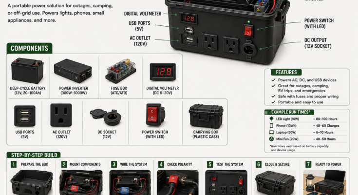
A portable battery box can keep essential devices operating during a blackout without the noise, fuel storage and carbon-monoxide danger associated with a gasoline generator.
A properly designed system may power:
- LED lighting
- Mobile phones
- Tablets
- Radios
- Internet equipment
- USB fans
- CPAP machines, after verifying requirements
- Laptops
- Small 12-volt appliances
The basic principle is:
Battery + correctly sized wiring + circuit protection + regulated outputs = portable emergency power
However, the infographic makes this project appear simpler than it really is. A deep-cycle battery can release enough current during a short circuit to melt wiring, ignite insulation or make tools red-hot. Lead-acid batteries may release hydrogen while charging, while lithium batteries require a compatible battery-management system and charger.
This should be treated as a serious low-voltage electrical project—not merely a battery placed in a plastic case.
What the Battery Box Does
The battery stores direct-current energy, usually at a nominal 12 volts.
Different outputs then use that energy:
- 12-volt socket: Supplies approximately battery voltage to suitable DC devices.
- USB module: Converts battery voltage into regulated 5-volt USB power or USB-C charging voltages.
- Inverter: Converts 12-volt DC into 120-volt AC.
- Voltmeter or monitor: Displays battery condition.
- Fuse block: Protects individual wires and circuits.
- Disconnect switch: Isolates the battery when the system is stored or serviced.
Whenever possible, use direct DC or USB outputs. An inverter consumes some power itself and loses additional energy during conversion.
Important Safety Warning
This project involves:
- High short-circuit current
- Battery acid or combustible electrolyte
- Hydrogen gas from some lead-acid batteries
- Possible lithium-battery fire
- Hot or melting wires
- Incorrect AC voltage
- Electric shock
- Battery overcharging
- Damaged electronics
Use components approved for the battery chemistry and intended application. Follow the battery, inverter, charger and fuse manufacturers’ instructions.
If you cannot determine cable size, fuse rating, grounding, inverter configuration or battery ventilation confidently, have the system assembled or inspected by a qualified technician.
Never connect this box to household wiring or plug its inverter into a wall receptacle.
Choose the Battery Chemistry
Flooded lead-acid battery
Advantages:
- Widely available
- Relatively inexpensive
- Familiar charging technology
- Can provide high current
Limitations:
- Heavy
- Contains corrosive acid
- Must remain upright
- May release hydrogen during charging
- Requires ventilation
- Should not be deeply discharged regularly
- Needs periodic maintenance
A flooded battery should not be sealed inside an airtight plastic case. OSHA guidance calls for adequate ventilation where battery charging could allow hydrogen to accumulate. OSHA battery guidance
AGM lead-acid battery
Advantages:
- Sealed construction
- Spill-resistant when used correctly
- Lower maintenance
- Common in portable power systems
Limitations:
- Still needs appropriate ventilation
- Heavy
- Sensitive to chronic undercharging
- Usable capacity is limited if long life is expected
- Requires an AGM-compatible charger
“Sealed” does not mean incapable of venting. An AGM battery can release gas through its safety valves during abnormal charging.
LiFePO₄ battery
Advantages:
- Much lighter
- Greater usable capacity
- Longer potential cycle life
- Lower voltage sag
- Faster charging when supported
Limitations:
- Higher purchase price
- Requires an internal or external battery-management system
- Requires a compatible charger
- Charging below the manufacturer’s minimum temperature may damage cells
- Damaged or counterfeit batteries can create serious fire hazards
Purchase a listed or reputable assembled battery with a suitable battery-management system. Do not construct a lithium pack from loose cells unless you possess the necessary training and test equipment.
Lithium-ion energy-storage incidents can involve delayed ignition or reignition after damage. NFPA energy-storage safety information
Do Not Use an Automotive Starting Battery
A starting battery is designed to deliver a large current for a short engine start and then be recharged quickly.
A backup box repeatedly discharges the battery over longer periods. Use a deep-cycle battery intended for that duty.
Repeatedly deep-cycling a starting battery can:
- Reduce its capacity
- Damage its plates
- Shorten its life
- Leave it unable to start a vehicle
Do not mix batteries of different chemistries, capacities, ages or charge states.
Calculate the Required Capacity
Battery capacity is commonly listed in amp-hours, but devices consume energy in watt-hours.
A rough nominal calculation is:
Nominal watt-hours=Battery voltage×Amp-hours\text{Nominal watt-hours} = \text{Battery voltage} \times \text{Amp-hours}
A 12.8-volt, 100Ah LiFePO₄ battery nominally stores:
12.8×100=1,280Wh12.8\times100=1,280\text{Wh}
A nominal 12-volt, 100Ah lead-acid battery is often described as:
12×100=1,200Wh12\times100=1,200\text{Wh}
But nominal energy is not the same as usable AC energy.
Account for:
- Permitted depth of discharge
- Battery age and temperature
- Inverter efficiency
- Inverter standby consumption
- Wire losses
- Device startup surges
- Battery-discharge rate
Use:
Estimated runtime=Nominal Wh×usable fraction×system efficiencyLoad watts\text{Estimated runtime} = \frac{\text{Nominal Wh}\times\text{usable fraction}\times\text{system efficiency}} {\text{Load watts}}
Example Runtime Calculation
Suppose a 100Ah lead-acid battery is limited to approximately 50% discharge for better longevity, and the inverter system operates at 85% overall efficiency:
1,200×0.50×0.85=510 usable Wh1,200\times0.50\times0.85=510\text{ usable Wh}
With a 50-watt laptop load:
510÷50=10.2 hours510\div50=10.2\text{ hours}
Real runtime may be lower because the laptop’s consumption changes and lead-acid capacity depends partly on discharge rate and battery condition.
For a 100Ah LiFePO₄ battery with an assumed 90% usable fraction and 90% efficiency:
1,280×0.90×0.90≈1,037 usable Wh1,280\times0.90\times0.90\approx1,037\text{ usable Wh}
At 50 watts:
1,037÷50≈20.7 hours1,037\div50\approx20.7\text{ hours}
These are planning estimates, not guaranteed runtimes.
Why the Infographic’s Runtime Claims Are Misleading
The image lists battery sizes from 20Ah to 100Ah but provides single runtime ranges. That is too broad to be useful.
A 20Ah battery contains roughly one-fifth the nominal energy of a 100Ah battery of the same voltage. Device charging also varies considerably.
A phone “charge” depends on:
- Phone-battery capacity
- Charging conversion loss
- Whether the phone is used while charging
- Cable efficiency
- Battery-box voltage
- USB module efficiency
Always calculate performance using the specific battery and load.
Choose an Inverter Carefully
The inverter must match:
- Battery voltage
- Continuous load
- Startup surge
- Battery’s permitted discharge current
- Cable capacity
- Fuse rating
- Intended appliances
Modified-sine-wave inverter
Usually less expensive, but it may cause:
- Buzzing
- Additional heat
- Motor problems
- Audio interference
- Incompatibility with sensitive equipment
Pure-sine-wave inverter
Generally preferred for:
- Medical devices
- Laptops
- Audio equipment
- Variable-speed motors
- Sensitive electronics
- Devices whose manufacturers require clean AC power
Check both continuous and surge ratings.
A 300-watt inverter cannot necessarily start a device labeled 250 watts because the startup surge may be much higher.
Understand the High DC Current
Low voltage does not mean low current.
A 1,000-watt inverter operating from a 12-volt battery may require approximately:
1,000÷(12×0.90)≈93 amps1,000\div(12\times0.90)\approx93\text{ amps}
That is before considering surge current.
This requires:
- Very short battery cables
- Large copper conductors
- Properly crimped lugs
- Correct terminal torque
- A high-interrupt-capacity fuse
- A battery capable of supplying the load
- Secure mechanical mounting
Do not use household extension cord wire, speaker wire or inexpensive jumper-cable conductors inside the box.
Inverter manufacturers specify battery cable and fuse requirements for each model. Use those specifications instead of selecting cable by inverter wattage alone. Victron DC-wiring guidance
Recommended Components
Core components
- 12-volt deep-cycle battery
- Chemistry-compatible charger
- Pure-sine-wave inverter
- Main battery fuse and holder
- Master battery disconnect
- Positive and negative bus bars
- Covered fuse block
- Battery monitor or voltmeter
- USB charging module
- USB-C Power Delivery module, if desired
- 12-volt socket
- Appropriately rated AC outlet assembly
- Ventilated protective enclosure
- Terminal covers
- Strain reliefs
- Cable glands
- Internal barriers
Wiring supplies
- Fine-stranded copper battery cable
- Appropriately sized branch-circuit wire
- Tinned copper where corrosion is a concern
- Adhesive-lined heat-shrink tubing
- Crimp-on cable lugs
- Insulated terminals
- Cable loom
- Rubber grommets
- Cable clamps
- Warning labels
- Correctly rated DC fuses
Tools
- Multimeter
- DC clamp meter
- Cable cutter
- Proper lug crimper
- Wire stripper
- Heat gun
- Torque wrench
- Drill and hole saws
- Deburring tool
- Insulated hand tools
- Safety glasses
- Protective gloves
Do not hammer-crimp large battery lugs or crush them with ordinary pliers.
A Safer Electrical Layout
The simplified wiring diagram should be expanded as follows:
Battery positive
    ↓
Main fuse near battery
    ↓
Master disconnect
    ↓
Positive bus bar
    ├── Fused inverter circuit
    ├── Fused USB circuit
    ├── Fused 12V socket circuit
    ├── Fused lighting circuit
    └── Fused monitoring circuit

Battery negative
    ↓
Battery-monitor shunt, if used
    ↓
Negative bus bar
    ├── Inverter negative
    ├── USB negative
    ├── 12V socket negative
    ├── Lighting negative
    └── Monitoring negative
Every smaller wire leaving the bus should have protection suitable for that wire and load.
A fuse protects wiring from overheating during faults; it is not simply an accessory for the connected device. Blue Sea Systems circuit-protection guidance
Step 1: Design the System Before Buying Parts
List every expected load:
| Device | Watts | Hours per day | Daily Wh |
|---|---|---|---|
| LED light | 10 | 5 | 50 |
| Phone charging | 15 | 2 | 30 |
| Router | 12 | 8 | 96 |
| Laptop | 50 | 3 | 150 |
| Total | 326 Wh |
Then account for:
- Desired number of outage days
- Conversion losses
- Battery-discharge limits
- Recharge availability
- Startup surges
- Future expansion
Do not size the system around “small appliances” as a vague category. Record the actual nameplate or measured consumption of every intended device.
Step 2: Select the Enclosure
The case must:
- Support the battery’s weight
- Protect the terminals
- Resist impact
- Provide appropriate ventilation
- Allow equipment cooling
- Keep metal objects away from terminals
- Provide strain relief for every cable
- Prevent the battery from moving
- Permit inspection and maintenance
The battery should be held with a rigid restraint—not merely wedged between wires.
Do not put an inverter into a tightly sealed box. Inverters generate heat and normally require clearance and airflow specified in their manuals.
Keep the system dry, but do not achieve water resistance by eliminating required ventilation.
Step 3: Plan the Panel Layout
Before cutting the case, arrange:
- USB ports
- 12-volt socket
- Voltmeter
- Switches
- AC receptacle
- Charging connector
- Cooling openings
- Main disconnect
- Fuse access
Keep AC and DC wiring physically separated where practical.
Position the outlets so connected plugs cannot be crushed when the lid closes. Protect rear terminals from accidental contact with the battery or tools.
Step 4: Cut and Finish the Openings
- Remove the battery and electronics.
- Mark each opening.
- Confirm clearance behind the panel.
- Drill pilot holes.
- Cut slowly.
- Deburr every edge.
- Install grommets or cable glands.
- Vacuum all plastic and metal debris.
- Test-fit each component.
- Remove the components before final cleaning.
A small metal shaving across battery terminals can create a destructive short circuit.
Step 5: Secure the Battery
Mount the battery upright unless its manufacturer permits another orientation.
Use:
- Battery tray
- Nonconductive restraint
- Heavy-duty strap
- Protective terminal covers
- Clearance around safety vents
- Acid-resistant containment where necessary
Do not drill into the battery case.
The battery must not shift when the box is:
- Lifted
- Carried
- Transported in a vehicle
- Placed on uneven ground
- Subjected to sudden braking
Remember that a 100Ah lead-acid battery may weigh around 60 pounds or more. Confirm that the case and handles can carry the finished system.
Step 6: Install the Main Fuse
The main positive fuse should be placed as close to the battery terminal as the applicable standards and equipment layout permit.
Its job is to protect the cable if it becomes shorted before reaching the distribution system.
The fuse must be selected according to:
- Cable ampacity
- Expected continuous load
- Inverter manufacturer’s requirement
- Battery’s possible fault current
- Fuse interrupt rating
- System voltage
- Enclosure temperature
The fuse rating must not exceed what the protected wire can safely carry. Blue Sea Systems fuse-selection guidance
Do not use an automotive blade fuse for a very high-current inverter unless it is specifically suitable for the required current and fault-interruption duty.
Step 7: Install the Disconnect and Bus Bars
Connect the main fuse to a DC-rated battery disconnect, then to a covered positive bus bar.
Install a separate negative bus bar.
Bus bars should be:
- Rated above the expected current
- Covered against accidental contact
- Mounted on a nonconductive surface
- Protected from loose tools
- Accessible for inspection
- Clearly marked positive and negative
Do not stack an excessive number of terminals directly on the battery posts.
Step 8: Wire the Inverter
Follow the inverter manufacturer’s exact requirements.
General sequence:
- Keep the inverter switched off.
- Install its dedicated positive fuse.
- Use the specified cable size.
- Keep positive and negative cables equally short where possible.
- Crimp and heat-shrink the lugs.
- Route cables away from sharp edges.
- Support cables so they cannot pull on terminals.
- Connect polarity correctly.
- Tighten terminals to the specified torque.
- Install protective covers.
Reverse polarity can destroy an inverter immediately. Loose connections increase resistance and heat. Manufacturer guidance stresses correct polarity, adequate cable thickness and tight connections. Victron inverter installation guidance
Step 9: Wire the USB and 12-Volt Outputs
Each branch circuit should have its own fuse.
For every output:
- Determine its maximum current.
- Select wire for that current and circuit length.
- Install a fuse that protects the wire and device.
- Connect through a suitable switch if desired.
- Insulate exposed terminals.
- Label the voltage and maximum output.
A 12-volt socket may follow battery voltage, which can range considerably depending on battery chemistry and charge state. Not every “12V” appliance tolerates that entire range.
Use a regulated DC converter for sensitive equipment.
Step 10: Install the Voltmeter or Battery Monitor
A simple voltmeter provides only a rough state-of-charge indication.
Voltage changes with:
- Battery chemistry
- Recent charging
- Active load
- Temperature
- Battery age
- Rest time
A shunt-based battery monitor is more useful because it can track current entering and leaving the battery.
If using a shunt, all loads and chargers normally connect to its system side so no current bypasses the measurement. Follow the monitor manufacturer’s diagram.
Do not depend on one generic voltage chart for every battery chemistry.
Step 11: Provide Safe Charging
The charger must match:
- Battery chemistry
- Nominal voltage
- Battery capacity
- Manufacturer’s charge profile
- Permitted current
- Temperature limitations
Do not charge a LiFePO₄ battery below its specified minimum temperature unless the battery includes approved low-temperature protection or heating.
For lead-acid systems:
- Charge in a ventilated location.
- Keep sparks and flames away.
- Protect eyes and skin.
- Do not obstruct safety vents.
- Inspect for swelling, leakage or heat.
- Keep vent caps functioning where applicable.
OSHA requires functioning vent caps during charging to reduce electrolyte spray hazards. OSHA battery-charging standard
Do not use an unregulated solar panel directly on the battery. Use a charge controller matched to the battery and array.
Step 12: Inspect Before Connecting the Battery
Before energizing:
- Verify polarity with a multimeter.
- Check every fuse rating.
- Pull-test every crimp.
- Confirm no cable is pinched.
- Inspect heat-shrink coverage.
- Confirm terminals are covered.
- Check disconnect operation.
- Verify inverter clearance.
- Remove loose tools.
- Remove metal shavings.
- Confirm ventilation.
- Confirm the battery is restrained.
Use insulated tools around battery terminals. Remove rings, watches and metal jewelry.
Step 13: Perform Initial Testing
Test progressively.
Test 1: No battery connected
Check continuity and confirm that positive and negative are not shorted.
Test 2: Main DC circuit
Connect the battery with all loads switched off. Watch for heat, odor, sparks or unexpected current.
Test 3: Individual branches
Test separately:
- Voltmeter
- USB ports
- 12-volt socket
- Lights
- Inverter
Test 4: Small load
Begin with an LED lamp or phone charger.
Test 5: Planned load
Operate the largest intended load while measuring:
- Battery voltage
- DC current
- Cable temperature
- Connection temperature
- Inverter condition
- Runtime
Stop immediately if a cable, terminal, fuse holder or switch becomes abnormally hot.
Safe AC Use
The inverter’s AC output is capable of dangerous shock.
Never:
- Backfeed a household receptacle
- Use a male-to-male “suicide cord”
- Connect the inverter to utility wiring
- Defeat grounding or GFCI protection
- Operate it in standing water
- Touch damaged cords
- Exceed its continuous rating
- Assume its internal protection covers external wiring
Neutral-ground bonding and GFCI behavior vary by inverter design. Follow the manufacturer’s installation instructions or consult an electrician.
A transfer switch or interlock for home circuits must be correctly installed and approved. This portable box should ordinarily power devices directly through its own outlets.
Appliances This Box Should Not Normally Power
A small 12-volt system is generally unsuitable for:
- Electric heaters
- Kettles
- Toasters
- Hot plates
- Microwave ovens
- Hair dryers
- Air conditioners
- Large refrigerators
- Well pumps
- Power tools with large startup surges
A 1,500-watt heater operated through a 12-volt inverter may require roughly 140 amps after losses. That can rapidly drain the battery and dangerously overload inadequate wiring.
Use stored battery energy for communication, lighting and modest essential loads—not resistance heating.
Maintenance Schedule
Monthly
- Check battery charge.
- Inspect for swelling or leakage.
- Test all outputs.
- Check cable tightness.
- Inspect fuses and covers.
- Clean ventilation openings.
- Confirm the charger operates.
- Record battery resting voltage.
Every three to six months
- Perform a controlled capacity test.
- Inspect the case and handles.
- Check cable insulation.
- Test the main disconnect.
- Inspect terminal corrosion.
- Verify monitor accuracy.
- Review the intended load list.
After every use
- Recharge promptly.
- Check for hot connections.
- Record energy consumed.
- Inspect the inverter fan.
- Clean and dry the enclosure.
- Replace damaged parts before storage.
Store according to the battery manufacturer’s temperature and state-of-charge recommendations.
Pre-Use Safety Checklist
- Battery chemistry and charger match
- Battery is undamaged and restrained
- Main fuse is installed near the positive terminal
- Every smaller branch is individually protected
- Fuse ratings protect the connected wiring
- Cable sizes follow equipment requirements
- Terminals and bus bars are covered
- All crimps are secure
- Polarity has been verified
- Inverter has adequate ventilation
- Battery ventilation meets its requirements
- No loose metal objects are inside
- AC and DC wiring are protected
- Maximum output is labeled
- The box will not be connected to home wiring
- A compatible charger is available
DIY Box Versus a Commercial Power Station
A homemade battery box offers:
- Replaceable components
- Custom output selection
- Serviceability
- Flexible capacity
- Educational value
A commercial portable power station usually offers:
- Integrated battery management
- Tested enclosure
- Built-in charging
- Displayed energy information
- Coordinated inverter and battery
- Fewer exposed high-current connections
- Product warranty
- Potential safety certifications
For many households, a certified commercial power station is the safer and simpler choice. A DIY system makes the most sense for someone who understands DC wiring and is willing to test and maintain it.
Final Takeaway
A DIY battery box can provide quiet, portable power for essential low-energy devices during an outage—but the battery itself is only one component.
A dependable system also requires:
- Correct battery chemistry
- Compatible charging
- Main and branch-circuit fusing
- Properly sized copper conductors
- Secure crimped connections
- Covered terminals
- Adequate ventilation
- Battery restraint
- Realistic runtime calculations
- Safe AC operation
- Routine inspection
Do not copy the infographic’s wiring diagram literally. It omits important details such as separate circuit protection, bus bars, a battery-monitor shunt, charging connections, ventilation and inverter-specific grounding requirements.
Build for the battery’s possible fault current—not only for the small devices you expect to power.