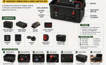
A portable solar power station can keep essential equipment operating when utility power is unavailable.
Unlike a gasoline generator, it can provide electricity without exhaust, fuel storage, or engine noise. Solar panels recharge a battery bank, while an inverter converts stored battery energy into the alternating-current power used by common household devices.
A basic system follows this energy path:
Solar panels → disconnect and protection → MPPT charge controller → battery bank → inverter → protected AC outlets
Separate fused DC circuits may also supply:
- USB charging ports
- 12-volt lights
- Radios
- Routers
- Small DC refrigerators
- Other compatible low-voltage equipment
However, the word “portable” can be misleading. Two large lead-acid batteries, a 2,000-watt inverter, cables, protective equipment, and a steel hand truck can easily create a system weighing well over 100 pounds.
It is better described as a movable emergency power station.
This guide explains how to plan one correctly, how to avoid dangerous wiring shortcuts, and how to determine what it can realistically power.
What This Solar Backup System Can Do
A properly designed system may support selected essential loads such as:
- LED lights
- Phones and tablets
- Laptop computers
- Internet modem and router
- Television
- CPAP machine, after manufacturer verification
- Security cameras
- Battery chargers
- Radio equipment
- Small fan
- Efficient refrigerator or freezer
- Certain small tools
- Other low-power appliances
Its limitations depend on four separate ratings:
- Inverter continuous and surge output
- Usable battery capacity
- Solar-array charging capacity
- Maximum current capacity of the wiring and protective devices
A 2,000-watt label on the inverter does not mean the system can supply 2,000 watts all day.
The inverter determines how much power can be delivered at one moment. The battery bank determines how long that power can continue. The solar panels determine how quickly the consumed energy can be replaced.
Important Safety Warning
This project combines:
- High-current battery circuits
- Potentially lethal AC voltage
- Solar panels that generate power whenever illuminated
- Batteries capable of releasing enormous fault current
- Heavy components that can shift during transportation
- Possible hydrogen gas from lead-acid batteries
- Fire risks from loose or undersized connections
A 12-volt battery is often described as “low voltage,” but a short circuit can still melt tools, ignite insulation, start a fire, or cause a battery to rupture.
Use listed components, manufacturer-approved installation methods, correct overcurrent protection, insulated terminal covers, properly crimped cables, and an enclosed electrical assembly.
Have the finished design inspected by a qualified electrician or off-grid solar professional, particularly if it will supply household wiring, medical equipment, or loads larger than basic electronics.
Never connect the inverter to a wall receptacle to energize a house. This dangerous practice, sometimes called backfeeding, can energize utility wiring and endanger workers or neighbors. Household circuits require approved transfer equipment and code-compliant installation.
The Main Components
1. Solar panels
The solar array converts sunlight into direct-current electricity.
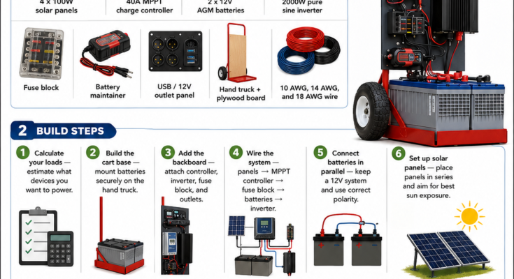
The illustrated system uses four nominal 100-watt panels for a total nameplate rating of 400 watts.
Actual production varies with:
- Sun angle
- Cloud cover
- Shade
- Panel temperature
- Dirt
- Wiring loss
- Charge-controller efficiency
- Battery state of charge
- Panel orientation
- Season
- Geographic location
A 400-watt array rarely produces exactly 400 watts continuously throughout the day.
The U.S. Department of Energy recommends mounting photovoltaic modules on a stable, durable structure capable of resisting wind, rain, hail, and corrosion. Orientation and tilt also affect annual energy production. DOE solar-system design basics
2. MPPT charge controller
A maximum power point tracking, or MPPT, controller regulates energy traveling from the solar panels to the battery.
It performs several jobs:
- Converts higher panel voltage to battery-charging voltage
- Tracks the array’s most productive operating point
- Controls bulk, absorption, and float charging
- Prevents uncontrolled battery overcharging
- Reports solar and battery information
- May disconnect charging when unsafe conditions are detected
The controller must match:
- Battery-bank voltage
- Battery chemistry
- Maximum PV open-circuit voltage
- Maximum PV short-circuit current
- Maximum charging current
- Array wattage
- Expected coldest temperature
A “40-amp MPPT” label alone does not confirm that four panels may safely be connected in series.
3. Battery bank
The battery bank stores energy for use when solar production is insufficient.
Possible battery types include:
- Flooded lead-acid
- AGM lead-acid
- Gel lead-acid
- Lithium iron phosphate, or LiFePO₄
- Other batteries specifically approved for stationary or mobile energy storage
Each chemistry requires different:
- Charging voltages
- Ventilation
- temperature limits
- depth-of-discharge limits
- fusing
- mounting
- monitoring
- maintenance
Never mix battery chemistries in one bank.
4. Pure sine-wave inverter
The inverter converts battery DC into household-style AC power.
The Department of Energy explains that inverters convert direct current into alternating current by electronically switching the direction of the input and shaping the output waveform. DOE inverter basics
A pure sine-wave inverter is generally preferred for sensitive electronics and motor-driven appliances.
The inverter should be evaluated for:
- Continuous output
- Surge output
- Input-voltage range
- Low-voltage shutdown
- Idle consumption
- Efficiency
- Grounding and bonding requirements
- AC outlet protection
- Environmental rating
- Manufacturer-required clearances
5. Overcurrent protection
Fuses and circuit breakers protect conductors and equipment from damaging current.
Typical protection points may include:
- Each parallel solar string
- Solar-array output
- Controller-to-battery circuit
- Each parallel battery string
- Battery-bank main output
- Inverter input
- Individual DC-load circuits
- AC output circuits
Protection must be sized for the conductors, equipment, expected current, and applicable electrical rules.
6. Disconnects
A disconnect allows sections of the system to be isolated for service or emergencies.
Useful disconnect locations include:
- Between array and controller
- Between controller and battery
- Between battery and inverter
- Before DC-load distribution
- At the AC output
The Department of Energy identifies disconnects as switches used to isolate all or part of a solar system safely. DOE tribal solar guide
7. Battery monitor
A true battery monitor normally uses a shunt installed in the battery’s negative circuit. It tracks current entering and leaving the battery bank.
Depending on the model, it can estimate:
- State of charge
- Current load
- Charging current
- Amp-hours consumed
- Energy consumed
- Remaining time
- Historical discharge data
A simple voltmeter is useful, but battery voltage alone does not always provide an accurate state-of-charge reading while the battery is charging or powering a load.
8. DC and USB output panel
A low-voltage output panel may provide:
- USB-A ports
- USB-C Power Delivery ports
- 12-volt accessory sockets
- Anderson-style connectors
- Dedicated lighting circuits
Every branch circuit needs an appropriate fuse and correctly sized conductor.
9. Frame or hand truck
The frame keeps components together and allows the system to be moved.
It should:
- Support the complete weight
- Prevent battery movement
- Protect wiring from impact
- Keep terminals covered
- Maintain inverter ventilation
- Resist tipping
- Include suitable wheels
- Provide lifting and tie-down points
- Keep live parts away from hands and tools
Do not mount exposed electrical components on an unprotected plywood board where rain, fingers, dropped tools, or metal objects can contact them.
Step 1: Calculate the Loads
Begin with the devices you actually need to operate.
For each device, record:
- Running watts
- Starting or surge watts
- Hours of daily use
- AC or DC operation
- Whether the load is safety-critical
Use the appliance label, manual, or a plug-in power meter.
Daily energy formula
[
\text{Daily watt-hours}=\text{Watts}\times\text{Hours used}
]
Example:
| Device | Running power | Daily use | Daily energy |
|---|---|---|---|
| Four LED lights | 40 W | 5 hours | 200 Wh |
| Router | 15 W | 10 hours | 150 Wh |
| Laptop | 60 W | 4 hours | 240 Wh |
| Television | 80 W | 3 hours | 240 Wh |
| Refrigerator | Variable | Estimated daily cycle | 800 Wh |
| Total | 1,630 Wh |
Add energy for:
- Inverter losses
- Controller losses
- Cable losses
- Battery inefficiency
- Inverter idle consumption
- Colder-than-expected batteries
- Unexpected outage duration
A design allowance of 15% to 30% is common for preliminary planning, but the exact value depends on the equipment.
In this example, a practical planning target might be approximately 2,000 watt-hours per day.
Step 2: Check the Peak and Surge Loads
Add the wattage of all devices that may operate at the same time.
Suppose the system must simultaneously power:
- Refrigerator: 150 watts running
- Laptop: 60 watts
- Router: 15 watts
- Lights: 40 watts
- Television: 80 watts
The combined running load is approximately 345 watts.
That appears easy for a 2,000-watt inverter. However, a refrigerator compressor may require several times its running power for a brief startup period.
Other surge-producing loads include:
- Freezers
- Pumps
- Power tools
- Fans
- Air compressors
- Microwave ovens
- Some medical equipment
Confirm that the inverter’s surge rating, duration, and battery-voltage limits match the appliance’s actual starting demand.
A large inverter connected to a small battery bank may shut down when battery voltage sags during a motor start.
Step 3: Size the Battery Bank
Battery capacity is often listed in amp-hours, but watt-hours make systems of different voltages easier to compare.
Nominal battery-energy formula
[
\text{Nominal watt-hours}=\text{Battery voltage}\times\text{Amp-hours}
]
Two 12-volt, 100-amp-hour batteries connected in parallel create a nominal:
[
12\text{ V}\times200\text{ Ah}=2,400\text{ Wh}
]
That does not mean all 2,400 watt-hours should be treated as usable.
Usable capacity
Usable energy depends on:
- Battery chemistry
- Recommended depth of discharge
- Age
- Temperature
- Discharge rate
- Inverter efficiency
- Battery condition
For example, if a lead-acid bank is conservatively limited to 50% discharge:
[
2,400\text{ Wh}\times0.50=1,200\text{ Wh DC}
]
If the inverter is approximately 90% efficient:
[
1,200\text{ Wh}\times0.90=1,080\text{ Wh AC}
]
This is only an estimate. Heavy loads may reduce available lead-acid capacity further.
A 100-watt continuous load might therefore operate for roughly:
[
1,080\text{ Wh}\div100\text{ W}=10.8\text{ hours}
]
Real-world runtime will usually be somewhat lower after idle consumption and other losses.
Lithium batteries
LiFePO₄ batteries often permit a deeper usable discharge and maintain voltage better under load, but they require:
- A compatible battery-management system
- Compatible charge settings
- Low-temperature charging protection
- Suitable overcurrent protection
- Correct cable and terminal ratings
- Manufacturer-approved mounting
Never replace lead-acid batteries with lithium batteries without reviewing every charging source and system setting.
Step 4: Decide Whether 12 Volts Is Appropriate
A 12-volt architecture is familiar and convenient for small systems, but current becomes extremely high as inverter power increases.
Use:
[
\text{Current}=\frac{\text{Power}}{\text{Voltage}}
]
At full 2,000-watt output, an ideal 12-volt inverter would draw:
[
2,000\text{ W}\div12\text{ V}=166.7\text{ A}
]
After inverter losses and lower battery voltage are considered, actual input current may approach or exceed 180 amps.
That requires:
- Very large battery cables
- Short cable runs
- High-current fusing
- Proper busbars
- Strong terminals
- Accurate crimping
- Careful voltage-drop control
A 24-volt system supplying the same power draws approximately half the current. A 48-volt system draws approximately one-quarter.
For a system expected to supply sustained loads near 2,000 watts, ask a qualified designer whether 24 volts would be safer and more practical.
Do not choose battery voltage based only on the batteries already available.
Step 5: Connect Batteries Correctly
Parallel connection
Connecting two matched 12-volt batteries in parallel keeps the bank at 12 volts while adding their amp-hour capacity.
Positive connects to positive.
Negative connects to negative.
Use batteries that are:
- The same chemistry
- The same nominal voltage
- The same model and capacity
- Similar in age
- Similar in condition
- At a similar state of charge before connection
For better current sharing, use equal-length, equal-size interconnecting cables and a balanced connection arrangement or properly rated busbars.
Each parallel battery string may require individual overcurrent protection so one battery cannot feed an uncontrolled fault in another string.
Series connection
Connecting two 12-volt batteries in series creates a 24-volt bank while amp-hour capacity remains unchanged.
Positive of one battery connects to negative of the next. The remaining free terminals become the 24-volt bank output.
Never connect a 12-volt inverter or controller to a 24-volt bank unless it is specifically rated for 24 volts.
Prevent reverse polarity
Reverse polarity can instantly damage:
- Inverters
- Charge controllers
- USB converters
- Battery monitors
- Other electronics
Before installing the final fuse:
- Verify every cable label.
- Check polarity with a meter.
- Confirm system voltage.
- Compare the wiring to the approved diagram.
- Make the final connection according to the manufacturer’s sequence.
Remove metal jewelry and use insulated tools around batteries.
Step 6: Size the Solar Array
The solar array must produce enough energy to recharge the battery while also supporting daytime loads.
A simplified estimate is:
[
\text{Daily solar energy}=\text{Array watts}\times\text{Peak-sun hours}\times\text{System factor}
]
For a 400-watt array with five equivalent peak-sun hours and a preliminary 0.75 system factor:
[
400\text{ W}\times5\times0.75=1,500\text{ Wh/day}
]
This does not guarantee 1,500 watt-hours every day.
Production may fall sharply during:
- Cloudy weather
- Smoke or haze
- Winter
- Partial shade
- Poor panel orientation
- High panel temperatures
- Rainy seasons
If the daily loads require 2,000 watt-hours while the array replaces only 1,500 watt-hours, the battery bank will gradually become depleted.
A resilient system should include:
- Reduced emergency loads
- More solar capacity where appropriate
- Additional battery storage
- An approved secondary charging source
- A low-battery conservation plan
Step 7: Choose Series, Parallel, or Series-Parallel Panel Wiring
The infographic shows four panels in series, but that arrangement is safe only if it remains within the charge controller’s electrical limits.
Panels in series
Series connection increases voltage while current remains approximately equal to one panel’s current.
Advantages may include:
- Lower wire current
- Reduced voltage drop
- Smaller conductor requirements for long runs
- Earlier MPPT startup in some systems
Disadvantages include:
- Higher DC voltage
- Greater shock and arcing risk
- Larger effect from certain shading conditions
- Possible controller overvoltage in cold weather
Panels in parallel
Parallel connection maintains approximately one panel’s voltage while currents add.
Advantages may include:
- Lower array voltage
- Better performance under some partial-shading patterns
- Compatibility with lower-voltage controllers
Disadvantages include:
- Higher current
- Larger conductors
- More parallel-string protection
- Combiner equipment
Series-parallel arrangement
Four matching panels can sometimes be configured as two panels in series per string, with two strings in parallel.
This may provide a useful balance of voltage and current, but it still must be calculated from the actual component specifications.
Step 8: Verify the Controller’s Maximum PV Voltage
Find the panel’s:
- Open-circuit voltage, or Voc
- Maximum-power voltage, or Vmp
- Short-circuit current, or Isc
- Maximum-power current, or Imp
- Temperature coefficient of Voc
When panels are connected in series, their voltages add.
If each panel has a Voc of 22.5 volts:
[
22.5\text{ V}\times4=90\text{ V}
]
That 90-volt value is measured under specified test conditions. Panel voltage rises as temperature falls.
Victron’s official MPPT guidance states that series-connected panel Voc values must be added and corrected for the coldest expected temperature. The result must remain below the charge controller’s maximum PV input voltage. Victron MPPT panel-matching guidance
Exceeding the controller’s PV-voltage rating may permanently damage it.
Use the controller manufacturer’s sizing calculator and local minimum design temperature. Do not assume that a controller rated “40 amps” can accept any 400-watt solar array.
Step 9: Size the Charge Controller
For a 400-watt array charging a nominal 12-volt battery, a rough output-current estimate is:
[
400\text{ W}\div12\text{ V}=33.3\text{ A}
]
Actual controller output depends on charging voltage, conversion efficiency, conditions, and controller limits.
A 40-amp controller may be appropriate in some designs, but verify:
- Maximum PV voltage
- Maximum PV short-circuit current
- Maximum allowed array wattage at 12 volts
- Required safety factors
- Battery charge-current limits
- Ambient-temperature derating
- Cable-terminal size
- Breaker and fuse requirements
The battery manufacturer may limit how quickly the battery should be charged. A controller safe for the array can still provide too much charge current for a small battery bank.
Step 10: Select the Inverter
Choose an inverter that provides:
- Correct battery voltage
- Correct AC voltage and frequency
- Sufficient continuous output
- Sufficient surge output
- Pure sine-wave output where required
- Low idle consumption
- Listed AC protection
- Appropriate environmental rating
- Remote power switch if desired
Avoid dramatically oversizing the inverter.
A 2,000-watt inverter may consume more energy at idle than a smaller inverter. If the system mainly charges phones, runs lights, and powers a laptop, a smaller inverter or direct DC charging may be more efficient.
Use DC outputs whenever practical. Converting battery DC into AC and then back into low-voltage DC through a device charger wastes energy.
Step 11: Size Conductors and Fuses
The infographic mentions 10-, 14-, and 18-AWG wire, but those sizes cannot be assigned safely without calculation.
Conductor size depends on:
- Maximum continuous current
- Fuse or breaker rating
- Cable length
- Acceptable voltage drop
- Insulation temperature rating
- Ambient temperature
- Bundling
- Enclosure conditions
- Terminal limitations
- Local electrical requirements
An 18-AWG conductor may be appropriate for a small fused control circuit. It is completely unsuitable as a battery cable for a large inverter.
High-current inverter conductors are often far larger than ordinary household wiring.
Fuse placement
The main battery fuse should generally be installed as close to the battery’s positive terminal as the equipment instructions and applicable rules require.
The goal is to protect the conductor between the battery and the equipment. If the fuse is mounted far from the battery, the unprotected cable can short against the frame before current reaches the fuse.
The fuse must have:
- Appropriate current rating
- Adequate DC voltage rating
- Sufficient interrupt rating
- Correct holder
- Protection from accidental contact
- Compatibility with the conductor
Never substitute an AC-only breaker or fuse into a DC circuit without an appropriate DC rating.
Step 12: Build the Cart Safely
Mount the batteries low
Position heavy batteries near the bottom to lower the center of gravity.
The frame must prevent movement:
- Forward and backward
- Side to side
- Upward over bumps
- During loading into a vehicle
Use nonconductive or protected restraints that cannot short the battery terminals.
Protect the terminals
Install covers over all positive terminals and busbars.
A dropped wrench across a battery can create an intense short circuit.
Enclose live components
Use proper enclosures for:
- Fuse blocks
- Busbars
- Disconnects
- Shunts
- Cable joints
- AC wiring
- Exposed controller terminals
Ventilated covers should prevent fingers, tools, and stored objects from reaching energized parts.
Separate AC and DC wiring
Route AC and DC conductors separately where practical. Protect every cable from:
- Sharp edges
- Abrasion
- Wheel movement
- Pinching
- Heat
- Water
- Strain at terminals
Use grommets, conduit, cable glands, clamps, and strain relief.
Maintain cooling clearance
Inverters and controllers produce heat.
Follow the manufacturers’ requirements for:
- Orientation
- Ventilation
- Clearance
- Maximum ambient temperature
- Fan airflow
Do not pack blankets, extension cords, or tools around the inverter.
Step 13: Provide Battery Ventilation
AGM batteries are often called sealed batteries, but that does not mean ventilation can be ignored.
Under abnormal charging, failure, high temperature, or relief-valve operation, lead-acid batteries may release gas.
Install and use them according to the battery manufacturer’s requirements.
Do not place lead-acid batteries:
- In a sealed plywood box
- Beside ignition-producing switches
- Directly beneath an inverter’s cooling intake
- In sleeping areas
- Where terminals can become wet
- Where children can access them
- Where a tipping battery could spill or short
Flooded lead-acid batteries require even more attention to ventilation, electrolyte, corrosion, and upright installation.
Lithium batteries have different hazards and should not be placed in a sealed, combustible cabinet simply because they do not normally produce hydrogen.
Step 14: Install the Battery Monitor
A shunt-based battery monitor is normally connected so every charge and load—except the monitor’s specified small positive lead—passes through the shunt.
If an inverter or charger is connected directly to the battery’s negative terminal instead of the system side of the shunt, the monitor will not measure that current correctly.
Program:
- Battery capacity
- Charged voltage
- Tail current
- Charge efficiency
- Peukert settings when applicable
- Low-state-of-charge alarms
Follow the monitor manufacturer’s instructions rather than relying on universal settings.
Step 15: Install the AC Output Safely
The inverter may include receptacles, or its output may supply a small protected outlet panel.
Depending on the inverter and local rules, the AC section may require:
- Overcurrent protection
- Ground-fault protection
- Proper equipment grounding
- Neutral-to-ground bonding in one defined location
- Strain relief
- Enclosure
- Correct receptacle type
- Correct conductor color and size
Neutral and grounding arrangements vary by inverter design. Do not create extra neutral-to-ground bonds without following the manufacturer’s instructions.
Use heavy-duty extension cords rated for:
- The current
- Cord length
- Environment
- Outdoor use where applicable
Do not run extension cords beneath rugs, through standing water, or through doorways where they can be crushed.
Step 16: Follow the Correct Connection Sequence
The required sequence varies by manufacturer, but many standalone controllers must recognize battery voltage before solar power is applied.
A typical procedure may be:
- Verify all disconnects are open.
- Confirm battery polarity and voltage.
- Connect the battery bank through appropriate protection.
- Power and configure the charge controller.
- Select the correct battery chemistry and charging profile.
- Connect the PV array through its disconnect.
- Verify charging operation.
- Connect DC loads.
- Connect and test the inverter.
- Energize one load at a time.
Follow the exact sequence in each component’s manual.
When shutting down, use the manufacturer’s specified reverse sequence.
Never disconnect a battery from an operating controller while the solar array remains energized unless the manufacturer explicitly permits it.
Step 17: Commission the System
Before using the system during an outage, conduct a controlled test.
Visual inspection
Check:
- Cable polarity
- Cable size
- Fuse ratings
- Fuse locations
- Terminal covers
- Crimp quality
- Cable strain relief
- Battery restraint
- Ventilation
- Grounding
- Enclosure security
- Panel connector compatibility
- Absence of exposed copper
Electrical checks
Measure:
- Individual battery voltage
- Complete bank voltage
- Array open-circuit voltage
- Controller input voltage
- Controller charging current
- Inverter input voltage
- Inverter AC voltage
- Voltage drop under load
Only qualified people should perform energized measurements.
Load test
Begin with a small load, such as an LED lamp.
Then test:
- USB and DC circuits
- Small AC electronics
- Expected continuous loads
- Refrigerator or other motor starting
- Maximum planned combined load
- Low-battery warning and shutdown behavior
Watch for:
- Hot cables
- Warm terminals
- Voltage collapse
- Inverter alarms
- Controller errors
- Unexpected odor
- Loose connections
- Battery heating
- Excessive fan operation
Stop immediately if a component smokes, swells, sparks, becomes unusually hot, or emits a strong odor.
What This Example System Might Power
The exact answer depends on battery capacity, not merely inverter size.
| Device | Typical power range | Important consideration |
|---|---|---|
| LED lamp | 5–15 W | Excellent emergency load |
| Phone charger | 5–30 W | Prefer direct USB/DC charging |
| Laptop | 40–100 W | Check charger rating |
| Router and modem | 10–30 W | Often suitable for extended use |
| Television | 50–150 W | Screen size and brightness matter |
| Fan | 20–100 W | Startup surge may occur |
| CPAP | 30–100+ W | Humidifier greatly affects use |
| Refrigerator | 80–250 W running | Compressor surge and duty cycle matter |
| Microwave | 1,000–1,800+ W input | Heavy short-duration battery load |
| Coffee maker | 700–1,500 W | High continuous heating load |
| Electric kettle | 1,200–1,800 W | Drains a small 12-volt bank rapidly |
| Space heater | 750–1,500 W | Usually impractical for a small battery bank |
| Air conditioner | Highly variable | Requires detailed surge and energy analysis |
Heating appliances may technically operate from the inverter but consume stored energy extremely quickly.
For emergency use, preserve battery capacity for lighting, communication, refrigeration, and medical needs rather than resistive space heating or water heating.
A Realistic Runtime Example
Assume the system has:
- Two 12-volt, 100-amp-hour AGM batteries in parallel
- 2,400 nominal watt-hours
- A conservative 50% usable discharge
- 90% inverter efficiency
Estimated usable AC energy:
[
2,400\times0.50\times0.90=1,080\text{ Wh}
]
Approximate runtimes before other losses:
| Average AC load | Approximate runtime |
|---|---|
| 50 W | 21.6 hours |
| 100 W | 10.8 hours |
| 250 W | 4.3 hours |
| 500 W | 2.2 hours |
| 1,000 W | 1.1 hours |
| 2,000 W | About 32 minutes theoretically |
The 2,000-watt example is especially optimistic. High-rate discharge, voltage sag, cable loss, inverter limits, battery age, and temperature may cause shutdown much sooner.
The inverter’s large power rating should be treated as peak capability—not a promise of long runtime.
Common Building Mistakes
Buying components before calculating loads
This often produces an oversized inverter, undersized battery, and inadequate solar array.
Using four panels in series without checking cold-weather voltage
Cold panel voltage may exceed the controller’s maximum input rating.
Installing an inverter fuse too far from the battery
The cable between the battery and fuse remains unprotected.
Using small automotive wire for the inverter
A high-power 12-volt inverter may draw well over 150 amps.
Connecting unmatched batteries in parallel
Different age, capacity, or condition can produce poor current sharing and early failure.
Leaving battery terminals exposed
A dropped tool can create a severe short circuit.
Assuming AGM means no ventilation
AGM batteries can still release gas under fault or abnormal charging conditions.
Mounting everything on open plywood
Exposed terminals and combustible backing create unnecessary contact and fire hazards.
Making a tall, top-heavy cart
The system may tip while moving across a threshold or uneven ground.
Using the battery maintainer as a universal charger
A maintainer may not have the capacity or charging profile needed for the complete bank. If grid charging is desired, use a charger correctly sized and approved for the battery chemistry.
Backfeeding a household outlet
Never power home wiring through a male-to-male cord or ordinary wall receptacle.
Treating the system as weatherproof
Most inverters, controllers, outlets, and batteries shown in DIY projects are not approved for rain.
Deployment During a Power Outage
- Move the cart to a dry, ventilated operating area.
- Keep it protected from rain and flooding.
- Position solar panels in a secure, unshaded location.
- Anchor panels against wind.
- Inspect connectors before energizing the array.
- Confirm battery state of charge.
- Start the inverter without loads.
- Connect essential devices one at a time.
- Monitor total power and battery current.
- Turn off nonessential loads.
- Shut the inverter down when AC power is not required.
- Reposition portable panels only when conditions are safe.
- Never deploy panels during lightning, high wind, or flooding.
Keep the battery system out of living and sleeping spaces unless its enclosure and battery manufacturer specifically permit the installation.
Maintenance Schedule
Monthly
- Inspect battery terminals.
- Check for corrosion or swelling.
- Confirm battery state of charge.
- Test the inverter.
- Inspect fuse holders.
- Check cables for abrasion.
- Verify that vents remain clear.
- Clean dust from equipment.
- Confirm that the cart remains stable.
Every three months
- Test the system under a realistic load.
- Inspect solar connectors.
- Check panel surfaces.
- Confirm controller settings.
- Review battery-monitor synchronization.
- Test low-battery alarms.
- Check DC and AC outlets.
- Exercise disconnects.
Every six months
- Inspect cable-terminal torque according to manufacturer instructions.
- Confirm battery balance.
- Examine tires and restraints.
- Check all labels.
- Review household load priorities.
- Test any grid-powered battery charger.
After every deployment
- Recharge the battery promptly.
- Record maximum load.
- Record minimum state of charge.
- Note inverter or controller alarms.
- Inspect for hot or discolored connections.
- Clean and dry the equipment.
- Correct problems before storage.
The Department of Energy emphasizes preventive operation and maintenance as important to long-term photovoltaic and storage-system safety and performance. DOE photovoltaic operation and maintenance guidance
Emergency Power Checklist
Before the outage
- Load calculation completed
- Battery fully charged
- Solar panels tested
- All cables labeled
- Correct spare fuses stored
- Extension cords inspected
- User instructions attached
- Critical devices tested
- Refrigerator startup tested
- Household members trained
- Fire extinguisher accessible
- Backup lighting available
During the outage
- System remains dry
- Ventilation remains clear
- Battery state of charge monitored
- High-power loads restricted
- Cords kept away from water
- Children kept away
- Panels secured against wind
- No household backfeeding attempted
- Essential medical needs prioritized
After the outage
- Battery recharged
- Solar panels cleaned and stored
- Cables inspected
- Fault history reviewed
- Energy use recorded
- Damaged components replaced
- Emergency plan updated
Is This System Truly Off-Grid?
Yes, if it is designed to operate independently without a utility connection.
But “off-grid” does not mean unlimited electricity.
A small 400-watt solar array and two batteries can provide useful emergency energy, but cloudy weather or heavy loads can consume stored power faster than the panels replace it.
The most reliable approach is to reduce energy demand:
- Use LED lighting.
- Charge devices directly from DC.
- Run the inverter only when needed.
- Keep refrigerators closed.
- Avoid electric heating appliances.
- Schedule large loads during strong sunlight.
- Monitor battery state of charge.
- Maintain a second safe charging option when practical.
Conservation is part of the power system.
Final Takeaway
A portable solar backup station can provide quiet, fuel-free emergency electricity, but safe construction requires more than mounting an inverter and two batteries on a hand truck.
A dependable system begins with:
- A written load calculation
- Adequate battery capacity
- A solar array matched to local conditions
- An MPPT controller sized for voltage, current, and cold weather
- An inverter matched to continuous and surge loads
- Correctly sized conductors
- Fuses placed near energy sources
- Protected terminals and busbars
- Proper battery restraint and ventilation
- Safe AC distribution
- Careful commissioning and regular maintenance
The most important correction to the illustrated design is this:
A 2,000-watt inverter on a 12-volt battery bank is a high-current installation. It may draw more than 180 amps under heavy load, making professional cable sizing, fusing, crimping, enclosure, and battery design essential.
Do not copy wire sizes or panel connections from a generic diagram. Verify every specification from the actual product manuals and have the finished system inspected.
Built correctly, this movable power station can keep lights, communications, refrigeration, laptops, and selected emergency equipment working.
Built carelessly, the same batteries and wiring can become a serious fire and shock hazard.
Calculate first. Protect every circuit. Cover every terminal. Test before the emergency.